PA28 · Limitations · 02 of 07
Airspeed Indicator Markings
- 01 · LOCKEDAirspeed Limitations
02 · READING NOW
Airspeed Indicator Markings
The airspeed indicator carries the limits on its face as coloured arcs and a red line, so you can read your margin at a glance.
At a glance
- Red radial line, never exceed154 KTS
- Yellow arc, caution range (smooth air only)125–154 KTS
- Green arc, normal operating range50–125 KTS
- White arc, flap down45–102 KTS
The four markings
Red radial line — 154 KTS, never exceed.
Yellow arc — 125 to 154 KTS, the caution range, for smooth air only.
Green arc — 50 to 125 KTS, the normal operating range.
White arc — 45 to 102 KTS, the flap down range.
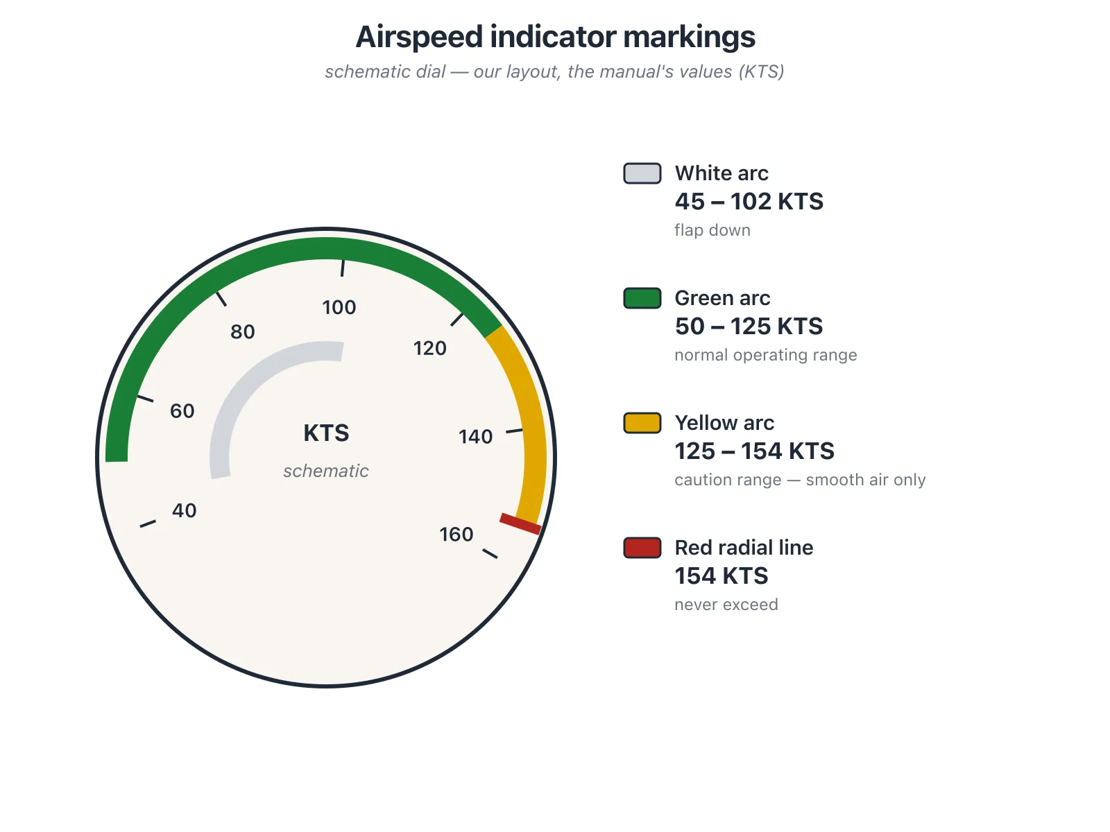
Figure: Airspeed indicator markings (redrawn).
Read the band edges against the airspeed limitations: the top of the white arc is VFE (102), the top of the green arc is VNO (125), and the red line is VNE (154).
Check yourself
What does the yellow arc cover, and when may you fly in it?
Where does the green arc start and end?
Which limit sits at the top of the white arc?
What speed does the red radial line mark?
Study aid — always fly your aircraft's current AFM/POH.
Source: Piper PA-28-181 Archer III Pilot's Operating Handbook and FAA Approved Airplane Flight Manual, Report VB-1611, p. 2-2, Rev. 24 (29 July 2010)
You're reading a free preview. Create an account to unlock every lesson, drill, and diagram.
- 03 · LOCKEDPowerplant Limitations
- 04 · LOCKEDPowerplant Instrument Markings
- 05 · LOCKEDWeight and Center of Gravity Limits
- 06 · LOCKEDManeuvers, Load Factors and Kinds of Operation
- 07 · LOCKEDPlacards