DA40NG · Operating Limitations · 02 of 23
Airspeed Indicator Markings
- 01 · LOCKEDAirspeed Limitations
02 · READING NOW
Airspeed Indicator Markings
The airspeed indicator restates the airspeed limits in colour, so that a glance at the needle answers the question the numbers answer more slowly. Learn the four markings as ranges with meanings attached, not as decoration on the dial face.
At a glance
- White arc60 – 98 KIAS
- Green arc66 – 130 KIAS
- Yellow arc130 – 172 KIAS
- Red line172 KIAS
What each marking means
The four markings
White arc, 60 to 98 KIAS — the operating range with the flaps fully extended.
Green arc, 66 to 130 KIAS — the normal operating range.
Yellow arc, 130 to 172 KIAS — the caution range, to be used only in smooth air.
Red line, 172 KIAS — the maximum speed for all operations, v_NE.
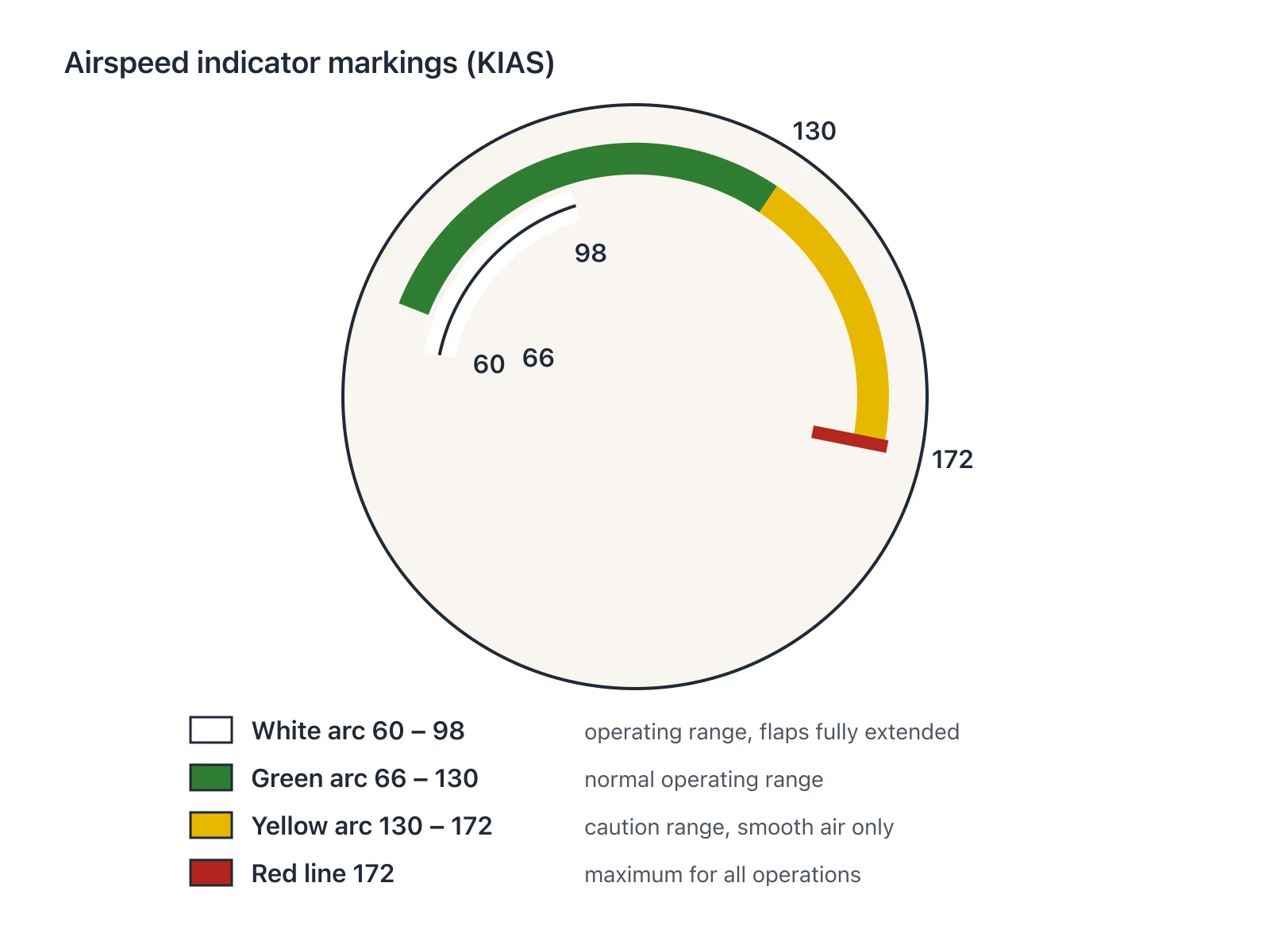
Figure: Airspeed indicator markings (redrawn).
Where the arcs overlap
The white and green arcs overlap between 66 and 98 KIAS, which is the band in which the aeroplane may be flown either clean or with the flaps fully out. Below 66 KIAS only the white arc is present; above 98 KIAS the flaps must be in, and the green arc runs on alone to 130 KIAS.
Notice that the top of the green arc, the bottom of the yellow arc and v_NO are all the same 130 KIAS, and that the top of the yellow arc, the red line and v_NE are all 172 KIAS. The dial is telling you the same two limits in a second language.
Check yourself
What are the lower and upper ends of the white arc, and what does that range represent?
What speed range does the green arc cover?
Under what condition may the yellow arc be used?
At what speed is the red line, and what limit does it correspond to?
Over what speed range do the white and green arcs overlap?
Study aid — always fly your aircraft's current AFM/POH.
Source: AFM Doc. No. 6.01.15-E, Rev. 4 (31 December 2024), p. 2-4, Rev. 4, 31-Dec-2024
You're reading a free preview. Create an account to unlock every lesson, drill, and diagram.
- 03 · LOCKEDEngine, RPM and Power Limits
- 04 · LOCKEDOil, Coolant, Gearbox and Fuel Temperature Limits
- 05 · LOCKEDFuel Pressure and Electrical Limits
- 06 · LOCKEDPropeller and Governor
- 07 · LOCKEDApproved Oils and Coolant
- 08 · LOCKEDEngine Instrument Markings
- 09 · LOCKEDElectrical and Fuel Quantity Markings
- 10 · LOCKEDRed Warning Alerts
- 11 · LOCKEDAmber Cautions and White Status Alerts
- 12 · LOCKEDMass Limits
- 13 · LOCKEDBaggage Limits
- 14 · LOCKEDDatum Plane and Centre of Gravity Limits
- 15 · LOCKEDApproved Manoeuvres and Load Factors
- 16 · LOCKEDAltitude, Restart and Crew Limits
- 17 · LOCKEDApproved Kinds of Operation
- 18 · LOCKEDMinimum Equipment for VFR, Night VFR and IFR
- 19 · LOCKEDApproved Fuels and Additives
- 20 · LOCKEDFuel Capacity and Indication Limits
- 21 · LOCKEDCockpit Placards
- 22 · LOCKEDTemperature Limits and Baffles
- 23 · LOCKEDBattery, Door, Electronics and Cabin Restrictions