P2006T · Limitations · 02 of 12
Airspeed Indicator Markings
- 01 · LOCKEDAirspeed Limitations
02 · READING NOW
Airspeed Indicator Markings
The airspeed indicator turns the airspeed limits into colour you can read at a glance in flight. This lesson covers the P2006T's ASI markings — the white, green and yellow bands and the blue and red radial lines — and what each boundary means.
At a glance
- White band54–93 KIAS
- Green band66–138 KIAS
- Yellow band138–171 KIAS
- Blue line84 KIAS
- Red line (lower)62 KIAS
- Red line (upper)171 KIAS
The colour bands
White band, 54–93 KIAS — its lower limit is V_S0 and its upper limit is the maximum allowable speed with flaps extended in the LND position.
Green band, 66–138 KIAS — the normal operating range: the lower limit is the stall speed with flaps up, V_S1, and the upper limit is the maximum structural cruising speed, V_NO.
Yellow band, 138–171 KIAS — manoeuvres must be conducted with caution and only in smooth air.
The radial lines
Blue line, 84 KIAS — best rate-of-climb speed with one engine inoperative.
Red line, 62 KIAS — minimum control speed with one engine inoperative and flaps set to T.O.
Red line, 171 KIAS — maximum speed for all operations.
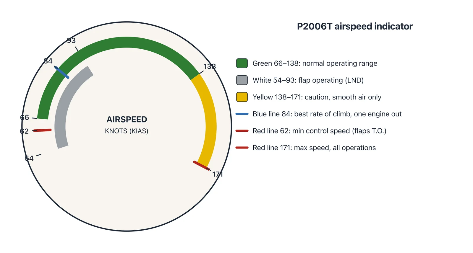
Figure: Airspeed indicator markings (redrawn).
Check yourself
What do the lower and upper limits of the white band represent?
What speeds bound the green band, and what does each end mark?
What does the blue line indicate, and at what speed is it set?
There are two red lines — what does each one mean?
Study aid — always fly your aircraft's current AFM/POH.
Source: P2006T AFM Doc. No. 2006/044, p. S2-7, 4th Edition Rev. 21 (15 Feb 2024)
You're reading a free preview. Create an account to unlock every lesson, drill, and diagram.
- 03 · LOCKEDPowerplant Limitations
- 04 · LOCKEDInstrument Markings
- 05 · LOCKEDWeight and Balance Limitations
- 06 · LOCKEDFuel Limitations
- 07 · LOCKEDOperating Envelope and Flight Load Factors
- 08 · LOCKEDOccupancy, Baggage and Gear Limits
- 09 · LOCKEDRequired Equipment (KOEL)
- 10 · LOCKEDApproved Operations and Manoeuvres
- 11 · LOCKEDAnnunciations: Warnings, Cautions and Advisories
- 12 · LOCKEDCockpit and Cabin Placards