SR20 · Limitations · 02 of 14
Airspeed Limitations and Indicator Markings
- 01 · LOCKEDCertification and Approved Operations
02 · Reading now
Airspeed Limitations and Indicator Markings
The five airspeed limits and the four markings that put them on the airspeed indicator. These are the speeds to know without looking anything up.
At a glance
- VO, operating maneuvering speed133 KIAS
- VNE, never exceed speed201 KIAS
- VNO, maximum structural cruising speed164 KIAS
- VFE 50%150 KIAS
- VFE 100%110 KIAS
- White arc, full flap operating range62–110 KIAS
- Green arc, normal operating range71–164 KIAS
- Yellow arc, caution range164–201 KIAS
- Red line201 KIAS
The limits
Airspeed limitations
VO, operating maneuvering speed: 133 KIAS
VNE, never exceed speed: 201 KIAS
VNO, maximum structural cruising speed: 164 KIAS
VFE 50%, flaps 50%: 150 KIAS
VFE 100%, flaps 100%: 110 KIAS
The markings
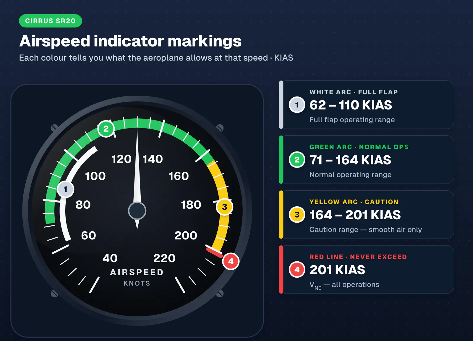
Figure: Airspeed indicator markings (redrawn).
White arc, 62–110 KIAS — the full flap operating range. Its bottom is the most adverse stall speed in the landing configuration; its top is the highest speed allowed with the flaps extended.
Green arc, 71–164 KIAS — the normal operating range. Its bottom is the stall at maximum weight, most forward CG, flaps retracted; its top is VNO.
Yellow arc, 164–201 KIAS — the caution range: operate with caution and only in smooth air.
Red line, 201 KIAS — VNE, the highest speed for all operations.
The markings are based on the normal static source calibration table. With the alternate static source selected, allow for the calibration difference between the normal and alternate sources.
Check yourself
What is VO, and what is VNO?
What are the two VFE values, and which flap setting goes with each?
What does the bottom of the white arc represent, and what does the bottom of the green arc represent?
In what conditions may you fly in the yellow arc?
What adjustment do the markings need when the alternate static source is in use?
Study aid — always fly your aircraft's current AFM/POH.
Source: Cirrus SR20 Airplane Flight Manual, P/N 44763-001, p. 2-4..2-5, AFM Rev. 1 (15-Jan-2025)
You're reading a free preview. Create an account to unlock every lesson, drill, and diagram.
- 03 · LOCKEDEngine Operating Limits
- 04 · LOCKEDFuel Limitations
- 05 · LOCKEDOil Grades and Engine Break-In
- 06 · LOCKEDEngine and Electrical Instrument Markings
- 07 · LOCKEDWeight, Center of Gravity and Load Factor Limits
- 08 · LOCKEDKinds of Operation Equipment
- 09 · LOCKEDAltitude, Temperature and Occupancy Limits
- 10 · LOCKEDFlap, Icing and Autopilot Limitations
- 11 · LOCKEDNavigation and Approach Limitations
- 12 · LOCKEDDisplay, Traffic and Weather System Limitations
- 13 · LOCKEDCabin, CAPS and Communication Limitations
- 14 · LOCKEDPlacards